Honda CM450 Bobber/Brat Bike (Making a Lower Shock Mount Bushing Puller.)
Deep Six Cycles
I have been working on modifying a Honda CM450 (Bobber/Chopper Custom thing). I am in the middle of mounting a fender to the Swing arm. I wished to weld the mounting bung for the fender struts to part of the lower shock mount on the swing arm. The only problem became the fact that there is a metal sleeved rubber bushing pressed into the lower shock mount. Heat from welding will absolutely result in this rubber catching fire. Since no reasonable amount of hammering with a punch or drift would budge the bushing I had to come up with another solution. I did not wish to take the swing arm off to press out the bushing in the H Press. Nor did I want to just weld it and have a melt down. Time to search through the scrap bin!
I was able to locate some 1"360 brass and a bit of 1-1/4 6061 aluminum. Game on! Please note some of the steps taken may have been skipped as this is not meant to be a tutorial for turning and lathe work. And some of the basic fundamentals were not photographed.
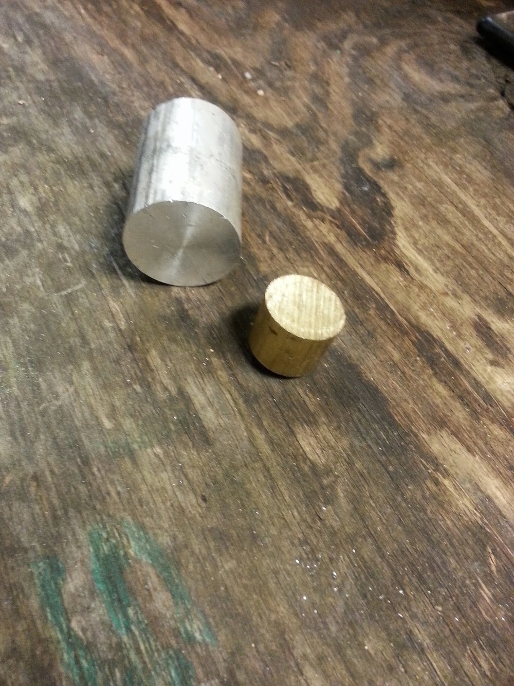
Here we have the 1" Brass and 1-1/4"Alum drops left over from another project.
I
I started with the brass first by taking a facing cut to true up the end of the part and eliminate saw marks.
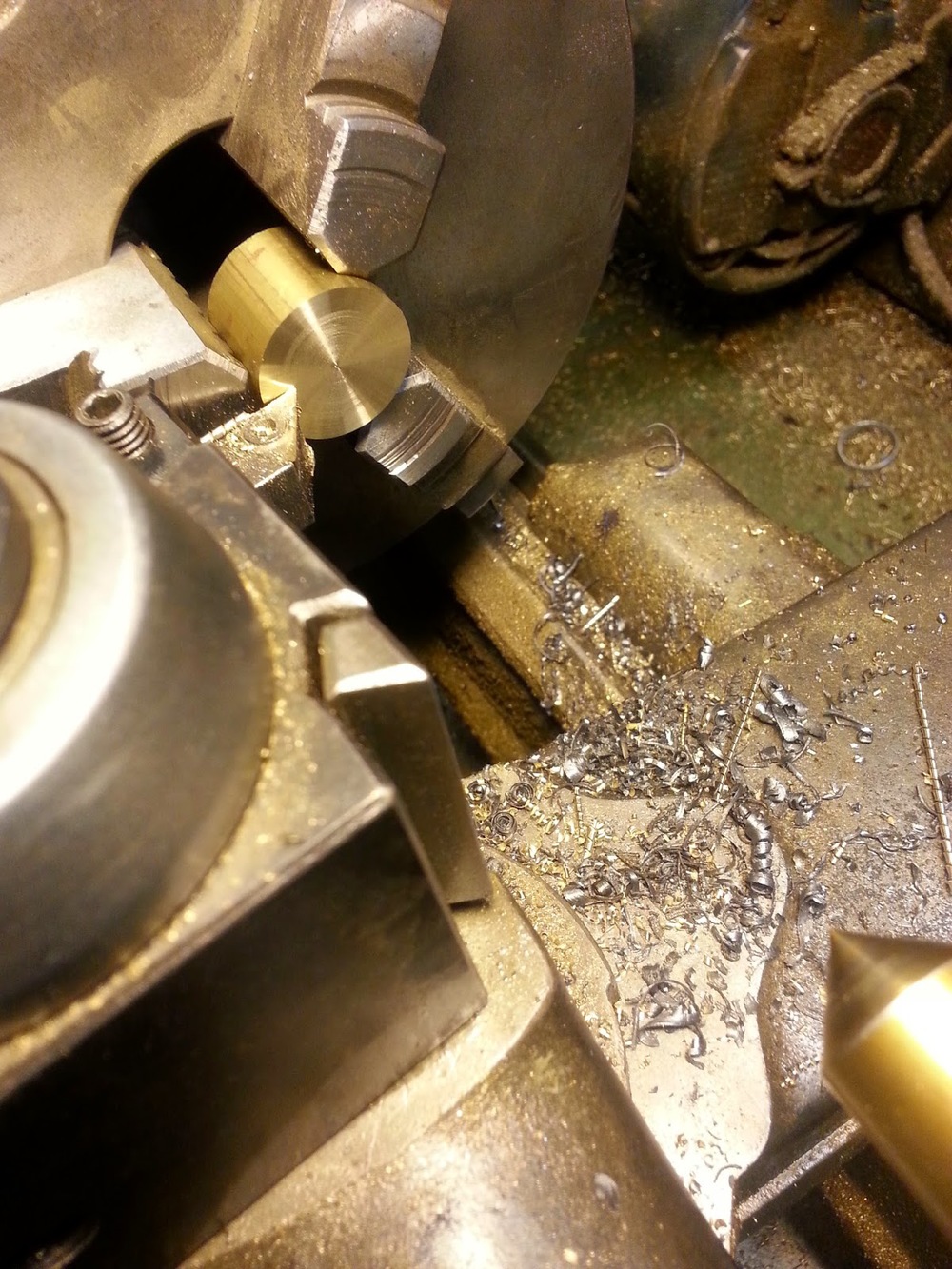
Here is the finished facing cut.

The part was then Center Drillled.

Next drilling with a 5/16 drill bit in order to be threaded with a 3/8-16 tap later on.

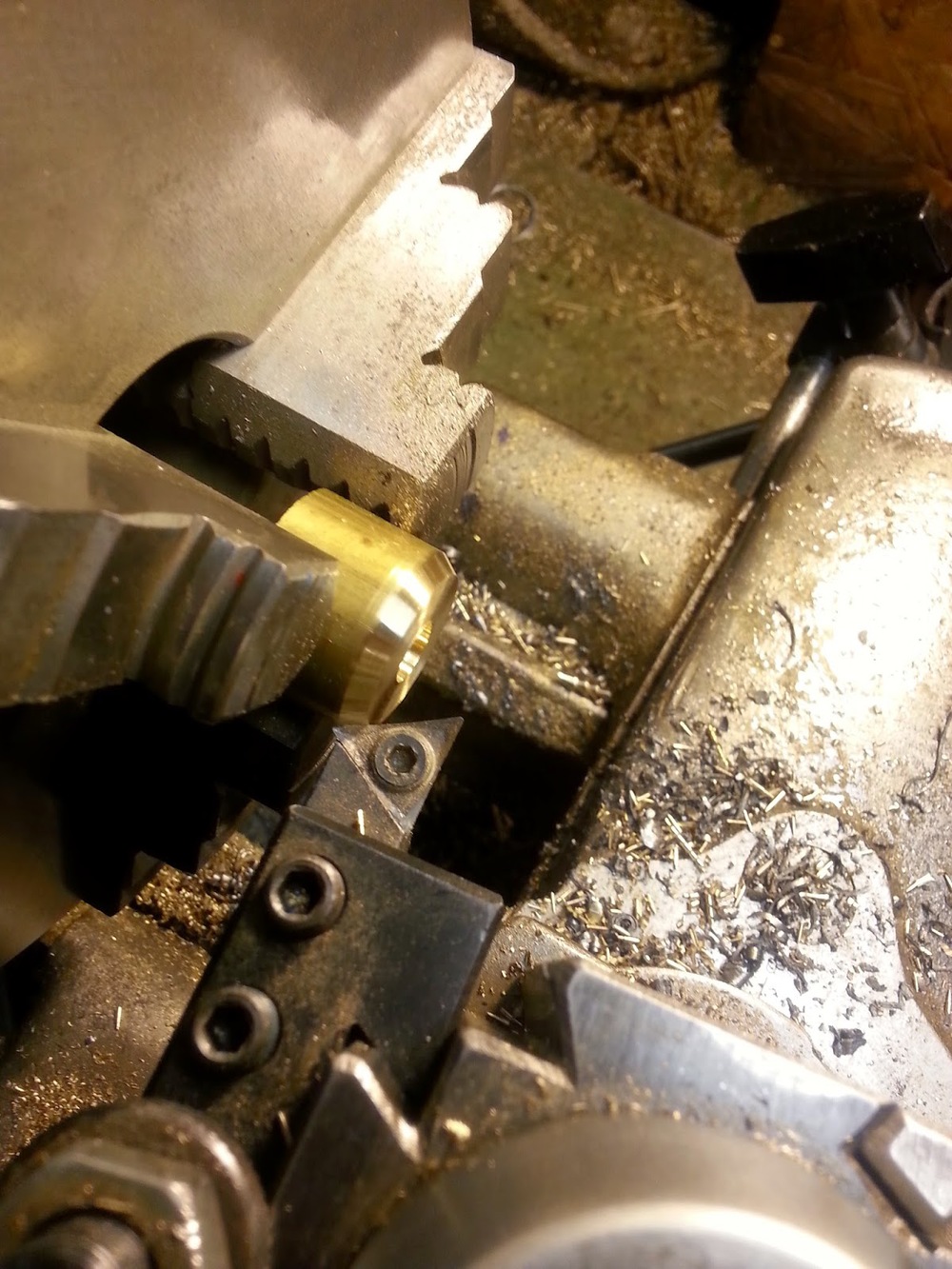
Next I added a heavy bevel to the outer edge. This will help the puller enter and find center of the i.d. of the shock bushing mount as it begins to displace the rubber bushing . It reduces chances binding.

Counter sink before tapping to eliminate the bur caused by drilling and ensure the tap enters concentric and on center to the drilled hole. This can reduce tap breakage. Others may find the tap creates a bur and prefer to counter sink after tapping. Both ways have worked for me. Next I threaded the part using the slowest turning speed with the back gear of the lathe engaged. Unfortunately I was in a rush and failed to photo the tapping operation.
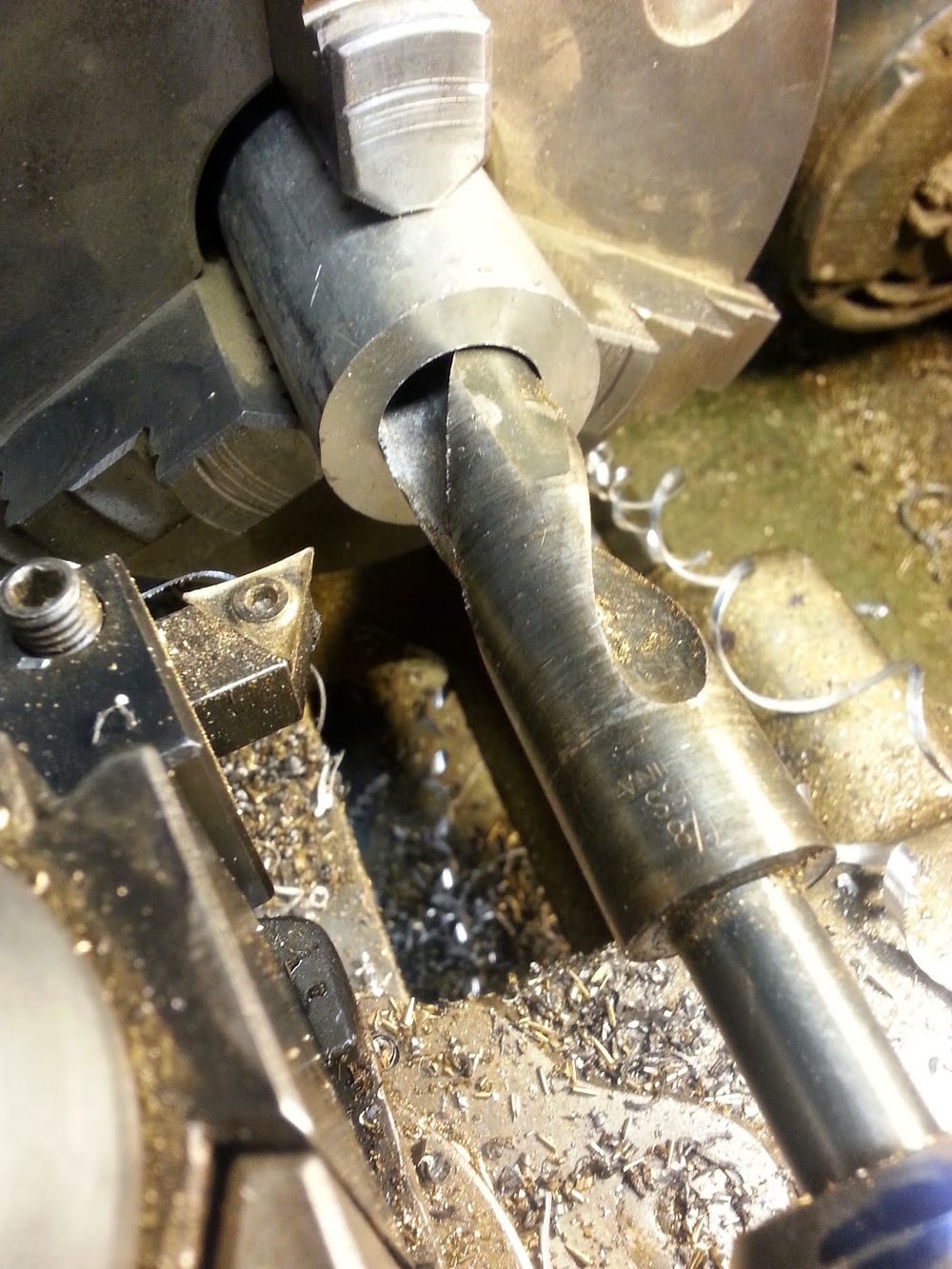
On to the aluminum. After facing, center drilling, I selected a W size drill bit. The letter size W bit is about .011 larger than 3/8. This will ensure that the 3/8 bolt that will be passing through the aluminum block will rotate freely with out binding or friction. Next I selected a large drill bit just under the od of the brass part I turned and began drilling the counter bore. Do not drill all the way thorough you only need the counter bore to be a little deeper than the lenght of the brass piece and the bushing you are removing. The goal is for the bushing and the brass to be able to enter the counter bore of the puller completely. The roof or ceiling of the counter bore will support a washer and bolt head on the other side (outside). This set up could have been done with the bolt passing through the brass and the threads in the aluminum or using a nut on the outside to draw the brass puller through the shock mount. But this would have required pulling the rear wheel to perform the work. Which I saw as an unnecessary step at this time.


Next I bored the counterbore out to .020 larger than the O.D. of the brass portion to allow for a nice friction free slip fit. This way I would not have to worry about the bushing binding and becoming caught inside the body of the puller once removed from the shock mount.

Here you can see the heavy chamfer entering the i.d. of the counterbore. This helps guide the bushing into the counterbore.

Here you can see the other side of the aluminum body a 3/8-16 bolt will pass through. The head of the bolt will ride against a washer on this flat surface. The bolt will pass through the aluminum puller body then though the rubber bushing and thread into the brass puller. Be sure you have the heavy chamfer on the brass puller facing the bushing. It is also imperative to make sure the bolt is long enough to thread all the way through your puller body before pulling begins. This will improve the wear of the threads in the brass and decrease the likelihood of damaging the threads. This tool is a great once in a while item. In daily use I would find another option for pressing a threaded top hat bung into the brass body of the puller. But I believe otherwise brass and aluminum are the perfect materials for this tool. They are soft and will not mar or score the shock mount itself. Aluminum could have been used in place of brass but you will likely have problems with the threads stripping. So if that is all you have on hand you will probably have to modify this design.

Here it is ready to extract the bushing. It worked great and did exactly what I needed it to. This tool could have been made a number of different ways. With the tools and materials I had on hand this was the easiest way for me to get it done. Hopefully this will spark an idea for some one that will help them out in a pinch some day. I am also aware that I could have bought a puller of some sort to do this or made a tool to work with my slide hammer. But again this took under 20 minutes and was completed with scrap and cheap material I had on hand.